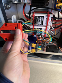
Electrical Wiring Supplement:
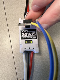
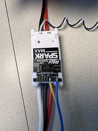
- Make sure that the data port alignment inserts are installed on any SparkMax ESC you use. This was done for you before delivery but always check before installing a dataport.
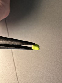
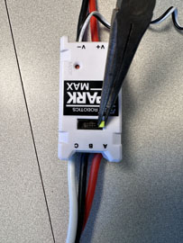
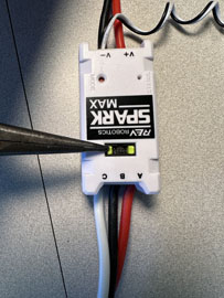
- Install the dataport in each ESC as shown and set it aside for later. Also note the Black and White signal input wire has been installed. If this is not done on your ESC do it now.
- Locate the two smaller XT-30 power leads with bare wire ends and the DCDC converter. These will power your receivers.
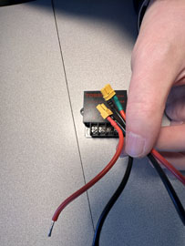
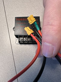
- Install both Red wires under the screw terminal labeled 5V + and tighten the screw down to hold them in place.
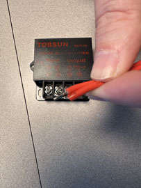
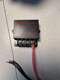
- Insert both Black wires under the screw terminal labeled 5V- and tighten the screw down to hold them in place.
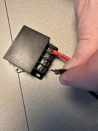
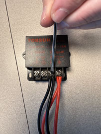
- Locate the larger XT60 power harness with bare wire leads. Insert the Red wire under the screw terminal labeled 12V+ and tighten the screw to hold the wire in place.
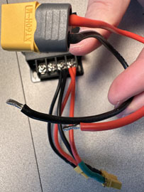
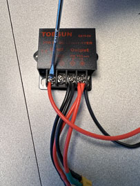
- Insert the Black wire under the screw terminal labeled 12V- and tighten the screw to hold the wire in place.
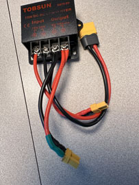
- Locate the two holes that allow access to the Circuit Breaker connector sockets. Use a 3/16 allen wrench to loosen the set screws and allow wire to insert fully into the sockets.
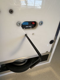
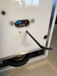
- Insert the short Black wire from the PDB into the circuit breaker socket on the front side. Insert the longer black wire from the PDB into the circuit breaker socket on the rear side. Make sure they are inserted fully then use the 3/16 allen wrench from the bottom and tighten the set screws you loosened in the previous step. Make sure these are tightened down very well. Pull on the wires to test that they will not come out easily from the sockets.
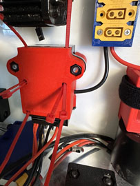
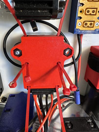
- Plug the XT 60 connector from the DCDC module into first port on the PDB as shown.
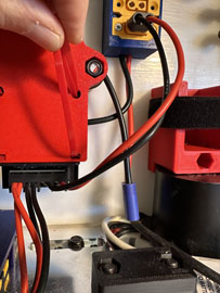
- Plug the XT 30 connectors from the DCDC into the receivers as shown. One connector should go to each received. It does not matter which socket. If you plug both connectors into one receiver no damage will occur but the second receiver will not receive power.
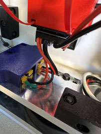
- Now is a good time to install the antenna leads into the antenna holder behind the ESCs.
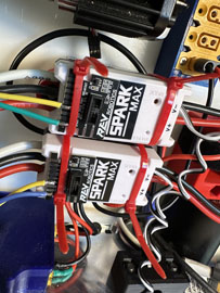
- Install the SparkMax ESCs into the CBM using zip-ties as shown. I Like to cut off any excess zip tie material for a cleaner look.
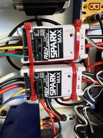
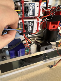
- Install the black signal cable with a multi wire terminal from the right motor into the right Sparkmax ESC. It goes in the socket under the data port and only fits in one orientation. Make sure it is fully seated.
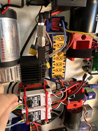
- Connect the 3-wire power connector from the right ESC to the right motor. Route all wires for a clean installation. You don’t want tangled messes to make troubleshooting difficult later.
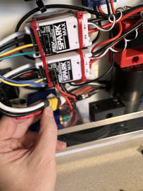
- Repeat the data cable installation for the left motor and ESC. Note that the cable and power wire will be routed beneath the air compressor.
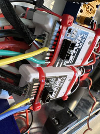
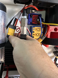
- Connect the left 3-wire connectors from the ESC and motor in the area shown under the compressor. This is a little difficult to reach but it is possible. You may find it helpful to use some needle nose pliers but take care not to damage the wire.
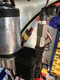
- Connect the right ESC power lead with XT60 connector into the second port on the PDB. The left ESC power lead will connect to the third port on the PDB.
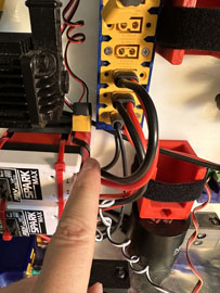
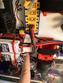
- Connect the AC-ESC XT60 connector power lead to the last port on the PDB as shown. Connect the 12V Fan XT60 connector power lead to the second to last port on the PDB as shown.
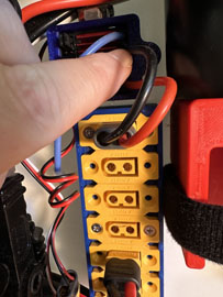
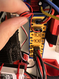
- Connect the Black (negative) lead from the air compressor into the Blue AC-ESC lead using the installed barrel connectors. Insert the small Red AC wire harness onto the pressure switch terminals using the installed spade connector.
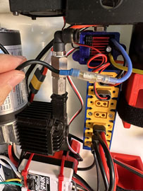
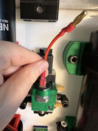
- Connect the Yellow AC-ESC lead to the Red AC wire harness lead using the installed barrel connectors. Install the long Red lead from the air compressor to the remaining pressure switch terminal using the installed spade connector.
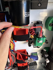
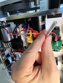
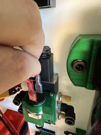
- Locate the Battleswitch harness with an XT60 connector on one end, an XT30 connector on the other and two wire leads with exposed ends. Connect the XT60 side to the PDB using the 4th port as shown. Connect the XT30 side to the 5-way air valve. I like to impart a coil to the long leads of the air valves by wrapping them around a pencil or screwdriver.
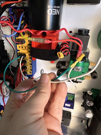
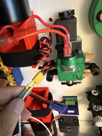
- The two bare leads from the Battleswitch harness plug into the center terminals on the battleswitch. Use a small flat screwdriver to loosen the terminals then tighten then back down after the wires are inserted. It does not matter which wire goes in which side. Choose the one that makes for the cleanest installation.
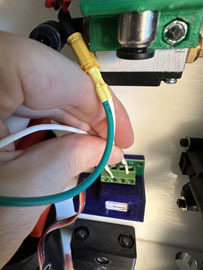
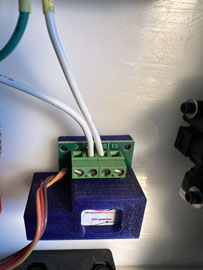
- This is a reference of the channel numbers for the RX10 pro receiver. In this picture channel 1 is at the top and 10 is at the bottom. Note that the receivers are installed upside down in the MRC-1000 chassis so that channel 1 is on the bottom and you will count up to channel 10 at the top.
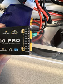
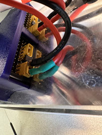
- Install the signal lead from the right ESC into channel 2 of the top receiver. Note that the Black wire should be closest to the XT30 port and aluminum sideplate.
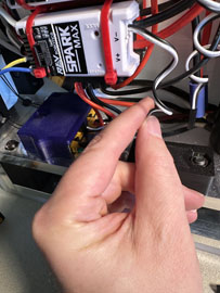
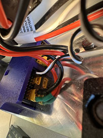
- Insert the signal lead from the left ESC into channel 3 of the top receiver. Again, pay attention to the orientation of the Black wire.
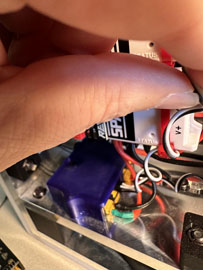
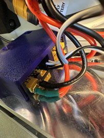
- Install the signal lead from the Battleswitch into channel 5 of the lower receiver. Note that the Brown wire should be closest to the XT30 power port and aluminum side panel. If you use a motorized mechanism with a separate ESC in your battle system you will likely want to use channel 3 as your control signal. That will use the left stick on the transmitter that does not spring to the middle as a proportional control.
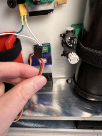
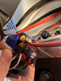
- Locate the servo extension and remove about 1/4” of the red wire from either end. Do not cut the orange or brown wires. We are disconnecting a 5V power source inside the AC-ESC from the control system with this step because it is not needed and we don’t want any interference.
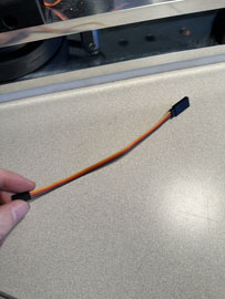
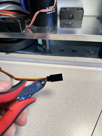
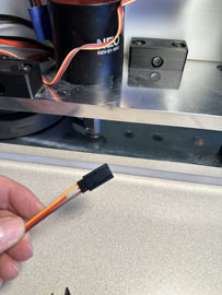
- Connect the modified servo extension to the signal lead on the AC-ESC as shown.
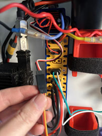
- Connect the other end of the servo extension to channel 6 on the lower received. Note that the Brown wire should be closest to the XT30 power port and aluminum side panel.
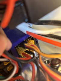
- This image shows the data port connection to the MagStop base using the MR-30 connectors. This will need to done after the base is mounted. You will need to connect and disconnect this connection every time your top plate is being installed or removed. Consider this in your design or pit strategy.
