Measurement
The engineering design process is both creative and technical. To spot and understand a problem and then move on to formulate possible solutions to that problem, an engineer has to be observant, open-minded, and creative. They also have to possess a strong set of scientific understandings and mathematical tools to move into the design, manufacturing, and testing phases of the engineering design process. Part of the technical aspect of this process is utilization of a standardized system of measurements, appropriate units, and indicators of accuracy and precision.
Utilizing a specific measurement and data reporting framework facilitates consistency, reliability, and communication of ideas. This is essential for regulatory compliance, global collaboration, and manufacturing processes. Therefore, this section will serve as a review of the basic measurement techniques needed to be successful during the various phases of the engineering design process.
Units and Standards
Most things that we measure include a description of that measurement as well as a size. The size of something is referred to as a “magnitude” while the description of that measurement is referred to as a “unit.” Units are a fundamentally important part of the measurement of an object; without units, we cannot be certain what the magnitude (number) means.
For example, if I told you that I ran “5” last night that doesn’t actually tell you anything meaningful. How far is 5? Perhaps it was 5 inches, or 5 feet, or 5 meters, or 5 miles; it could be anything! When looking at the measurements in the last sentence, you get a better feel for how big the 5 actually is. This is because those measurements included units. Therefore, everything we measure in science and engineering requires both a magnitude and a unit.
There are several systems of units in the world, but the three most common are the English or Imperial Units, the Metric Units, and the SI Units. Engineers often refer to English units as SAE (Standard American English) and the metric and SI units are referred to as ISO (International Organization for Standardization). These systems of units are built up by smaller sets of base units, which are defined in precise and reproducible ways. The precise and reproducible nature of the base units implies that the unit systems are standardized. This means that everyone will have the same size measurement for one base unit, no matter where they are in the world when making the measurement. Other units within the systems are derived algebraically from the base units of the system. The chart below lists the most common base units for all three of the systems mentioned above.
***Note that there are no English Unit equivalent measures
for Electrical Current and Amount of Substance.***
| Physical Quantity Being Measured | English Units | Metric Units | SI Units |
| Length | Foot (ft) | Meter (m) | Meter (m) |
| Mass | Slug | Kilogram (kg) | Kilogram (kg) |
| Time | Second (s) | Second (s) | Second (s) |
| Electrical Current | * | Ampere (amps) | Ampere (amps) |
| Temperature | Fahrenheit (°F) | Celsius (°C) | Kelvin (K) |
| Amount of a Substance | * | Mole (mol) | Mole (mol) |
| Luminous Intensity | Candlepower (cp) | Candela (cd) | Candela (cd) |
Most scientists and engineers around the world, including the US, use the SI system of units. This system is an internationally recognized and accepted system of units. One of the main reasons the SI unit system was so universally adopted was to make communication across borders more consistent, allowing data to be shared between scientists without translation or conversion errors. Another reason for the universal adoption of SI units was that none of the measurements were based on the arbitrary construction of the human body or other such constructs. Rather, all units in the SI system are accurately defined by physical quantities that are definite, thus leading to superior standardization. Further, no measurements in the SI unit system are based upon concepts that are not scientifically feasible. For example, zero Kelvin is the coldest theoretical temperature something can ever achieve because at that point it would contain zero thermal energy; you simply cannot go below zero as opposed to negative temperatures seen on Fahrenheit and Celsius scales. Also, the SI unit system is based upon powers of 10, much like the metric system, which makes mathematical manipulation far easier.
SI Prefixes
Being that the SI units are based upon powers of ten, it became convenient to find a way to symbolize different magnitudes using prefixes in front of the units. These are called the SI prefixes. The chart below represents several of the more common SI prefixes used in science and engineering, though this list is not exhaustive.
| SI Prefix | Number of Base Units |
| Giga (G) | billion (1,000,000,000) |
| Mega (M) | million (1,000,000) |
| kilo (k) | thousand (1000) |
| hecto (h) | hundred (100) |
| deca (da) | ten (10) |
| deci (d) | tenth (0.10) |
| centi (c) | hundredth (0.01) |
| milli (m) | thousandth (0.001) |
| micro (μ) | millionth (0.000001) |
| nano (n) | billionth (0.000000001) |
Unit and Prefix Conversions
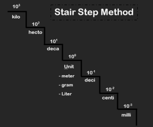
Sometimes we need to convert from one SI unit prefix to another. To do is typically a simple matter of moving the decimal place in the number. Students often use the “Stair Step Method” to do so.

*When moving UP the stairs — count how many stairs you are moving and divide by that many powers of ten — or just move your decimal point that many places to the LEFT!
*When moving DOWN the stairs — count how many stairs you are moving and multiply by that many powers of ten — or move your decimal point that many places to the RIGHT!
There are other times when we need to change from one unit or unit system to another. This is more complicated and requires the use of fractions and dimensional analysis. Dimensional analysis is the process of checking your units to see if they are correct, mathematically. So, when we are switching from one unit to another, or one unit system to another, we need to multiply and divide by conversion factors so that we cancel units we don’t want and arrive at the units we do want.
Angular Measurements
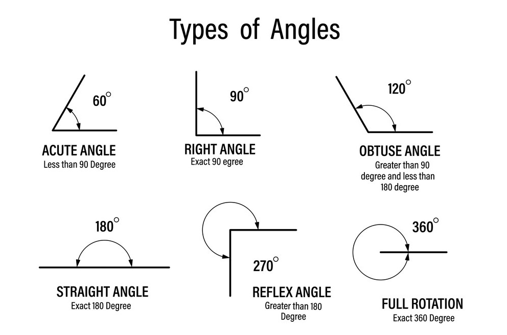
As you may recall, a full circle can be divided into 360 equal parts called degrees. Therefore, a degree is a unit of angular measurement representing 1/360th of a circle. Sometimes objects have angular measurements representing fractions of a full degree. These measurements are often represented with full-degree measurements and decimal measures included to represent the fraction of the remaining degree past the last degree. For example, an angle could be 125.5°, where the angle is halfway between 125° and 126°. Some common angle types are illustrated below.

In some applications, it is convenient to use non-decimal-based methods to indicate angular measurement. One common alternate form of angular measurement is the degree/minute/second form. Here, a full circle is still divided into 360 equal size degrees. Each degree can be further divided into 60 equal-sized “minutes” of arc. The minutes can then be further divided into 60 equal “seconds” of arc such that there are 3600 seconds of arc in one full degree. You can recognize this system if you see a number that looks like this: 180°45’30”. Here the number before the degree symbol (°) is the number of full degrees in the measurement. The number before the minute symbol (‘) is the number of full minutes after the last degree. Finally, the number before the seconds symbol (“) is the number of full seconds after the last minute of angular measure.
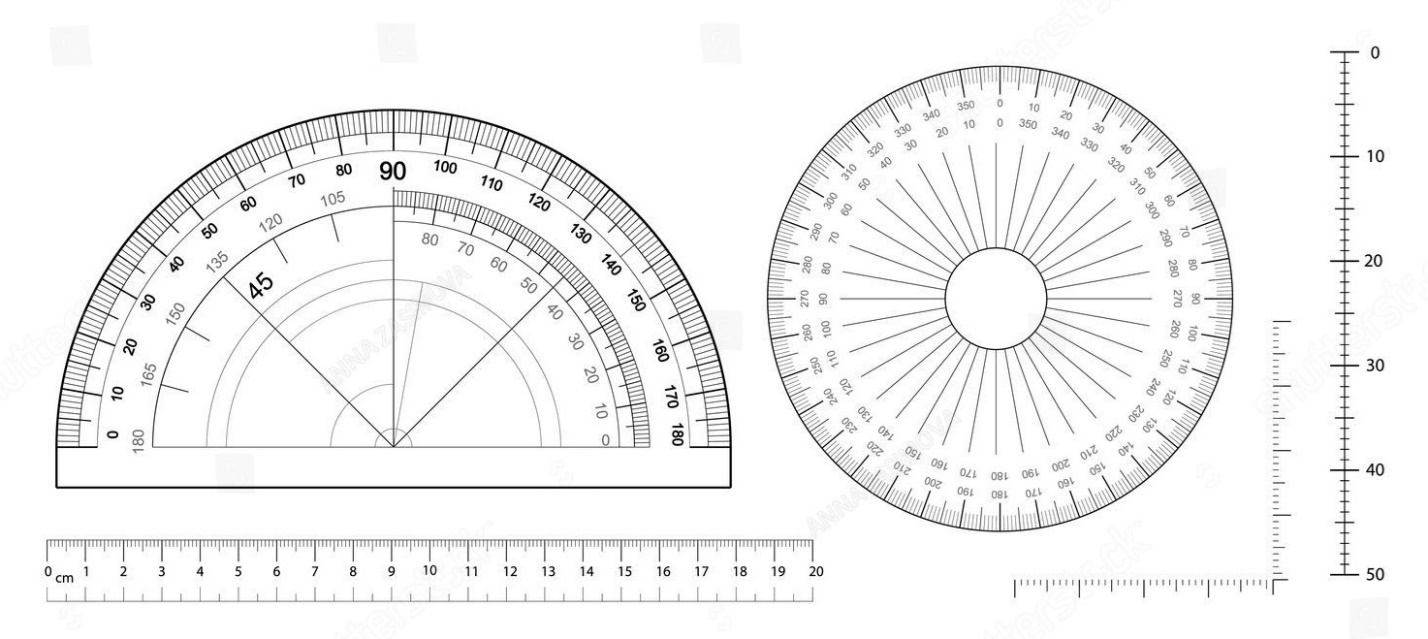
The image below illustrates measuring devices, two types of protractors, that can be used to measure angles.

This video illustrates how to use a protractor to measure angles – https://www.youtube.com/watch?v=c3ILHIJXj4o&ab_channel=TheDouceHouse
Significant Figures
When making or using measurements to design and construct something, it is important to keep track of tolerances. Tolerance is the permissible amount of variation in measurements and basically represents the amount of allowable tooling error. Since all measurements have error, due to innate limitations of tools, it makes sense that we specify the acceptable limits. It is also important that there exists a universally accepted way to communicate tolerance in measurements, this way engineers can make their designs, communicate them, and know that manufacturers will understand how to actually make the design within acceptable specifications. One of the most universally accepted methods of documenting the precision of measured values is through the use of Significant Figures. Significant figures are numbers, or digits, that we know to be measured precisely. These measurements are known to be precise to the decimal level they are recorded. To further communicate tolerances, engineering design drawings also include text-based documentation of tolerance levels in the form of “±” typically found in the title block of the drawing.
Significant Figures, or the precision of measurements, is typically represented by the number of decimal places in that measurement. The more numbers there are after the decimal, the more precise the measurement is and the less the number of decimals the less precise. This makes sense because if I am recording a measurement such as 1.005 cm, I am indicating that the measurement was taken down to the thousandths of a centimeter. However, if I record my measurement as 1.0, I am indicating that I only measured down to the tenths place, which is much less precise than measuring to the thousandths.
There are two different situations and sets of rules that need to be considered when considering significant figures. First, lets consider the situation where you are the person that is creating and recording the numeric data. In this situation, there is really only one simple rule that needs to be followed. While recording measurements, you must always measure to one decimal place beyond the smallest division of the scale you are using. In doing so, the last digit is estimated because it lies between division lines of the scale. So, if I measure and record the number 3.146, there are four numbers that are considered significant figures. The 3, 1, and 4 are significant because I know withing good confidence that they are correct because there are scale divisions on my measuring tool that indicate their precision. The 6 is also significant, because it is the first estimated digit beyond the scale.
The other situation where significant figures need to be well understood is when you are the person reading somebody else’s data or reviewing their engineering drawings. In this situation, you did not take the measurements yourself and need a system in place so that you can understand the precision of the measurements you have been given. The following rules are applied in this situation:
- All nonzero digits are considered significant.
For example, 658.9 has four significant figures and is precise to the tenths place.
- All zeros that are found between nonzero digits are considered significant.
For example, 6100.9 has five significant figures and is precise to the tenths place.
- Leading zeros, those to the left of the first nonzero digit, are not significant.
For example, 0.129 has three significant figures and is precise to the thousandths place.
- Trailing zeros for a whole number that ends with a decimal point are significant.
For example, 650. has three significant figures and is precise to the ones place. Had the decimal not been included after the “0” and the number was simply written as 650 there would only be two significant figures with precision down to the tens place.
- Trailing zeros to the right of the decimal are significant.
For example, 12.00 has four significant figures and is precise to the hundredths place.
- Exact numbers and irrationally defined numbers such as “e” or “π” have an infinite number of significant figures.
- All numbers in the coefficient of any value written in scientific notation are considered significant.
For example, 2,200 can be written in scientific notation to reflect two, three, and four significant figures depending on the actual amounts of precision in the measurement.
2.2 x 10³ has two significant figures
2.20 x 10³ has three significant figures
2.200 x 10³ has four significant figures
This video is a great review of accuracy,
precision, and measuring with significance: https://www.youtube.com/watch?v=b38hFWvEjwI&ab_channel=MichaelFarabaugh
Calculations with Significant Figures
Sometimes calculations need to be made using measurements that have significance. A set of rules exists for allowing various mathematical processes to occur without compounding precision errors within the measurements. Also, numbers generated through calculation often require rounding. So, rules for how we can round and still maintain the proper level of precision are also key. If these rules are not followed, measurement precision will be lost and this could lead to failed implementation of a design during manufacturing processes. The following rules outline how we should perform mathematical processes with significant figures.
Addition and Subtraction
When adding or subtracting significant figures, the number of decimal places in your final answer should be equal to the number of decimals in your limiting term. The limiting term is the measurement with the least number of decimal places.
For example, 2.000 + 1.0 would equal 3.0. In this case, we are only allowed one number after the decimal because 1.0 is our limiting term.
Multiplication, Division, Trigonometry, and Other
All other mathematical operations, aside from addition and subtraction, follow a different rule. When performing these other mathematical operations, the final answer must have the same number of significant figures as the limiting term. Here we actually count the number of significant figures, not the number of decimal places specifically.
For example, 8.000 / 2.0 would equal 4.0. In this case, we have two significant figures in our final answer because there are two significant figures in the limiting term, 2.0.
Rounding Rules
The examples above were simple and required no rounding, but this is not always the case. Therefore, the following rules must be followed for rounding. Rounding in this case is not the always the same as what you may have learned in a mathematics course. We utilize a system called “scientific rounding” that helps ensure that the rounding process doesn’t increase error over multiple calculations and rounding processes.
- When the digit to the right of the one being rounded to is less than 5, the remaining digit stays the same (rounds down).
For example, 7.84 rounded to the tenths place would become 7.8.
- When the digit to the right of the one being rounded to is greater than 5, the value rounds up.
For example, 7.86 rounded to the tenths place would become 7.9.
- When the digit to the right of the one being rounded to is exactly 5, with no nonzero digits following it, the value is rounded so that the final digit is an even number. Otherwise, if there are nonzero digits following the 5 the number being rounded is rounded up.
For example, 7.85 rounded to the tenths place would become 7.8.
However, 7.85001 rounded to the tenths place would become 7.9.