Waves and Radio Communications
Waves are a fundamental concept in physics, representing the transfer of energy through space. From the ripples on a pond to the electromagnetic waves carrying signals to our wireless devices, waves play a crucial role in our understanding of the physical world. In this section, we will explore the characteristics, types, and properties of waves and their applications to telecommunications.
Basics of Wave Motion
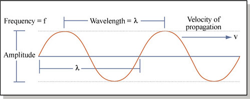
Waves can be described as oscillations that travel through a medium or through space. The basic components of a wave include the amplitude (A), wavelength (λ), frequency (f), and wave speed (v). The amplitude is the maximum displacement from the equilibrium position and is measured in meters (m). The wavelength is the distance between successive points on the wave and is also measured in meters (m). The frequency is the number of oscillations per unit time, measured in Hertz (Hz). Finally, the wave speed is the rate at which the wave propagates through matter or space and is measured in meters per second (m/s).
Types of Waves
Waves can be classified into two main categories: mechanical waves and electromagnetic waves.
- Mechanical Waves are waves that require a medium (some sort of material substance) to propagate and transfer energy. These waves cannot travel through empty space (a vacuum). There are two primary types of mechanical waves:
- Transverse Waves – In these waves the particles of the medium oscillate perpendicular to the direction of the wave speed. Examples include the “S” wave you see when you shape a rope back and forth while the other end is fixed in location as well as some types of water waves, and some forms of earthquakes.
-
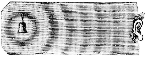
- Longitudinal Waves – The particles of the medium oscillate parallel to the direction of the wave speed. Examples include the compression waves you see when you stretch a slinky out length wise and move the end back and forth along the same direction as the stretch. Another example is a sound wave.
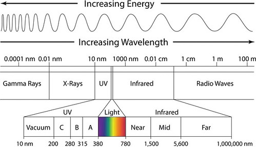
- Electromagnetic Waves are waves that do not require a medium and can propagate through a vacuum. These waves are comprised of oscillating electric and magnetic fields that are transverse and mutually perpendicular to each other. They include radio waves, microwaves, infrared radiation, visible light, ultraviolet radiation, X-rays, and gamma rays. This range of electromagnetic (E&M) waves is called The Electromagnetic Spectrum and represents an infinite gradient of frequencies.
- Radio Waves have the longest wavelengths, lowest frequency, and carry the least energy of all E&M waves.
- Gamma Rays have the shortest wavelengths, highest frequency, and carry the most energy of all E&M waves.
Radio Frequency Signals (Radio Waves)
Radio frequency signals (RF), or simply radio waves, play a pivotal role in modern engineering, serving as the backbone for wireless communication systems, radar systems, medical devices, and countless other applications. Understanding the importance of RF signals is fundamental for engineers across various disciplines. This section explores the significance of RF signals in engineering and their applications in RGL.
In RGL, robots are controlled with wireless remote-control transmitters. In this application, RF signals travel between the transmitter in the remote control and the receivers in the robot and carry information about the desired function the robot needs to perform. Receivers are electronic devices that pick-up RF signals separate the radio signals from one another to convert specific signals into specific bits of data or commands. A transmitter is an electronic device that generates and sends out the radio signals containing the data and commands for the receiver.
RF signals are electromagnetic waves with frequences ranging from about 3kHz to 300GHz. These signals propagate through space and are widely used for communication, sensing, and control purposes. The RF signals used for RGL have a frequency of 2.4GHz, a frequency commonly used for wireless communications and remote-control applications. The behavior of RF signals is governed by the principles of electromagnetism, including Maxwell’s equations and wave propagation theory.
Despite their widespread use, RF signals pose several challenges for engineers including interference, propagation losses, and spectrum congestion. These issues can occasionally be witnessed during RGL activities when the receivers have poor connection to their transmitters. At this point, the remote control will warn of low RF signal or even signal loss. Addressing these challenges requires a strong understanding of electromagnetism and wave propagation theory, efficient use of antenna designs, and intelligent spectrum management strategies. A brief overview of electromagnetism and wave propagation theory is provided below to give insight into how RF signals work.
Wave Interference and Superposition
In the vast realm of physic and engineering, the phenomenon of wave interference and superposition plays a fundamental role in understanding and manipulating wave behavior. Understanding how waves interact when they overlap is essential for a wide range of applications, from designing antennas and optical devices to studying seismic waves and musical acoustics. The first thing to consider is wave interference.
Wave interference occurs when two or more waves meet at a point in space. Depending on their relative amplitudes and phases, interference can result in the reinforcement or cancellation of wave energy. The superposition principle, a fundamental concept of wave theory, states that the total displacement of a medium at any point and time due to the presence of multiple waves is the algebraic sum of the displacements caused by each individual wave. This leads to the idea that there are two main types of interference:
- Constructive Interference – occurs when waves of the same frequency and in-phase alignment meet. In-phase refers to a situation where crests and troughs line up, see the image below. This results in an increase in the overall amplitude of the wave. Mathematically, this can be expressed as ATotal = A1 + A2 + … + An where ATotal is the total amplitude, and A1, A2, …, An are the individual amplitudes of the interfering waves.
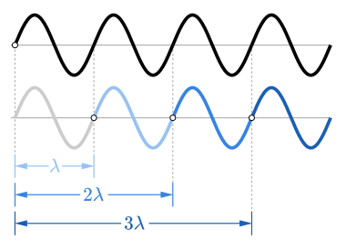
- Destructive Interference – occurs when waves of the same frequency and out-of-phase alignment meet. Out-of-phase refers to a situation where crests and troughs are misaligned, see the image below. This leads to a reduction or cancellation of the overall amplitude. Mathematically, this can be expressed as ATotal = A1 – A2 – … – An where ATotal is the total amplitude, and A1, A2, …, An are the individual amplitudes of the interfering waves.
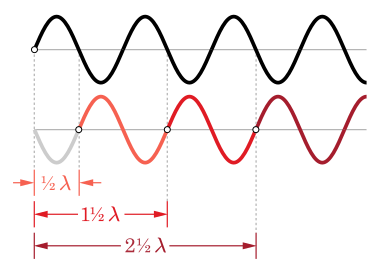
The implications for the concepts of interreference and superposition are numerous in practical application. In radio frequency engineering and antenna design, constructive interference is utilized to enhance signal strength, while destructive interference can be used to minimize interference from unwanted signals. In RGL, great care must be taken with regard to the placement of the receivers’ antennae so that they don’t cross and produce unwanted interference. Further, electrical wiring and other RF components within and outside of the robot chassis can produce unwanted interference as well.
Propagation Losses
Since RF signals propagate through various environments, they encounter numerous obstacles and losses that degrade signal quality. Understanding these propagation losses is crucial for designing reliable wireless systems and optimizing communications performance. To that end, a good understanding of the different types of RF signal propagation losses, their causes, and mitigation strategies is essential.
The first type of propagation loss to consider is called Path Loss. Path loss, also known as free-space loss, refers to the attenuation of RF signals as they propagate through space without encountering any obstacles or reflections. The amount of path loss is primarily influenced by the distance between the transmitter and the receiver and the frequency of the RF signal itself. Mathematically, path loss can be expressed as:
where:
-
-
- PL(d) is the path loss in decibels (dB)
- d is the distance between the transmitter and receiver in meters (m)
- f is the frequency of the RF signal in Hertz (Hz)
- PL0 is the path loss at a reference distance (usually 1 meter) and frequency
-
The next type of loss is called Free-Space Path Loss (FSPL). FSPL is a specific case of path loss that occurs when RF signals propagate through a vacuum or air without encountering any obstacles. It is calculated using the following equation:
where is the wavelength of the RF signal.
In addition to free-space loss, RF signals experience additional losses when propagating through different environments. These can be quite complicated to calculate for and require advanced mathematical modeling. For now, an awareness of these types of loss situations is sufficient for our design needs.
- Obstructions – buildings, trees, and terrain obstacles can block or attenuate RF signals, leading to shadowing and diffraction losses.
- Multipath Fading – reflections, refractions, and scattering of RF signals from surrounding objects result in multipath propagation. This causes signal fading and phase distortions.
- Atmospheric Attenuation – atmospheric gases, moisture, and particulates absorb and scatter RF energy, causing attenuation at higher frequencies. This is especially true during adverse weather conditions.
- Ground Reflections – RF signals reflected from the ground can interfere with the direct signal, causing destructive or constructive interference and affecting signal strength and quality.
- Faraday Cage – when a conductive material, such as wire mesh or metal plates, surrounds and encloses a receiver or transmitter, this shields the enclosed space from external electromagnetic fields and can prevent signals, such as RF, from entering the enclosed space.
Spectrum Congestion
The RF spectrum serves as a vital resource for wireless communication, accommodating a wide range of applications such as cellular networks, Wi-Fi, Bluetooth, and satellite communication, etc. However, with the exponential growth in wireless devices and services, the RF spectrum has become increasing congested. RF spectrum congestion refers to the condition where the available frequency bands are heavily utilized, leading to increased interference, degraded performance, and challenges in spectrum allocation. There are several factors that contribute to RF spectrum congestion, including:
- Explosive growth of wireless devices. The proliferation of smartphones, wireless sensors, and other technologies has significantly increased demand for RF spectrum utilization.
- Ubiquitous connectivity – the need for continuous connectivity, both indoors and outdoors, has led to the deployment of wireless networks in various environments. This father saturates the RF spectrum and leads to congestion.
- Legacy communication systems and inefficient spectrum utilization practices contribute to spectrum wastage and elevate congestion issues to new levels.
- Emerging technologies, such as 5G networks, autonomous vehicles, and smart cities introduces additional demands on the RF spectrum.
To address the RF spectrum interference, propagation losses, and congestion issues, engineers employ various mitigation strategies. The section below outlines many of the modern idea associated with increasing communication reliability in the RF spectrum.
Mitigation Strategies
- Minimize the potential for radio interference by eliminating extraneous RF sources as much as feasible.
- Optimize antenna placement for signal coverage and minimize the path loss by maximizing the direct line-of-sight path between the transmitter and receiver.
- Apply diversity techniques such as spatial diversity (using multiple antennas) and frequency diversity (operating at multiple frequencies).
- Mitigate multipath fading and enhance signal robustness.
- Adjust transmitter power levels based on channel conditions, optimizing signal strength while conserving energy and reducing interference.
- Use adaptive filters and diversity combining to compensate for signal fading and improve receiver performance in fading channels.
- Utilize spectrum sharing technology to enable efficient utilization of underutilized spectrum bands and mitigate congestion.
- Implement advanced modulation schemes and spectrum-efficient protocols to enhance the spectral efficiency and maximize throughput and capacity.
- Include spectrum management policies, like licensing frameworks and reassignment strategies, to optimize spectrum allocation and utilization.
RF signal losses pose significant challenges in wireless communication systems, affecting signal coverage, reliability, and performance. Understanding the causes and characteristics of RF losses is essential for engineers to design effective wireless networks and optimize communications links. Also, knowledge of the causes of RF losses helps engineers and policymakers develop strategies to optimize spectrum utilization. By employing appropriate mitigation strategies and using advanced technologies, engineers can overcome RF losses and build resilient wireless systems capable of supporting a wide range of applications.