Electricity, Magnetism, and Circuits
In the intricate tapestry of modern engineering, there exists an inseparable duo that plays a pivotal role in shaping the technological landscape we inhabit today: electricity and magnetism. These two intertwined phenomena affect nearly every aspect of modern life because of their connections to technological advancements.
This section delves into the significance of comprehending electricity and magnetism within the realm of engineering. From the simplest of electronic circuits to the most complex network-based communication systems, the principles of electricity and magnetism serve as the bedrock upon which engineering innovations are built. As we begin this exploration, we will unravel the relationships between electric and magnetic fields, detailing the mysteries that have fueled centuries of scientific inquiry and engineering progress.
The understanding of electricity and magnetism is not a mere academic pursuit; rather, it is an essential toolkit for engineers seeking to navigate the complexities of their craft. Whether designing cutting-edge electronics, developing efficient power systems, or innovating in the field of telecommunications, engineers must wield a deep understanding of these phenomena to address the challenges of our interconnected and electrified world.
Moreover, this section will illuminate the historical milestones that have led to our current understanding of electricity and magnetism. From the groundbreaking experiments of Coulomb and Faraday to the practical applications of modern-day engineers, we will trace the evolution of knowledge that has shaped our ability to harness these forces for the betterment of our world.
Electric Charge and Coulomb’s Law
Electric charge is a fundamental property of matter, and understanding its behavior is crucial in studying electricity. Further, electric charge gives rise to electric forces and thus the ability to do work with electrical energy. This reality has made the understanding of electrical charge important in the engineering of technological advancements.
Specifically, electric charge is a property of particles such as electrons and protons, which are the building blocks of atoms. There are two types of electrical charge: positive and negative. Electrons carry a negative electrical charge and protons carry a positive charge. It should also be noted that objects of like charge repel each other while objects of opposite charge attract to each other.
Phenomena such as electrical attraction and repulsion have been known for centuries. Perhaps one of the earliest discoveries of this behavior was made by an ancient Greek philosopher named Thales of Miletus (624-546 BCE) who recorded that when amber (a hard, translucent, fossilized resin from trees) was vigorously rubbed with fur, a force was created that cause the fur and the amber to be attracted to each other. He also noticed that the amber and fur could then affect other nonmetallic objects even though they had not been in contact.
Later, an English physicist named William Gilbert (1544-1603) studied this attractive force using various substances. He noticed that metals never exhibited these forces, whereas minerals did. He also noted that electrified amber would repel another piece of electrified amber. This suggested that there were two types of electrical properties, which we now understand as electric charge.
Further study of electrical forces by the French physicist Charles Augustine de Coulomb (1736-1806) helped further deepen our understanding of charges and the interactions they create. Coulomb’s Law describes the quantitative relationship between electric charge and the electric force between charged objects. Coulomb discovered that the magnitude of electric force depended directly upon the amount of electric charge possessed by the interacting objects and inversely upon the square of the distance between them. In honor of his work, the SI unit of electrical charge was named the coulomb with a symbol of a capital “C.” One coulomb of charge is equal to the total charge of approximately 6.242×10¹⁸ electrons!
Here,
- Fe is the magnitude of the electrostatic force between two charged objects
- q1 and q2 are the magnitudes of the charges
- r is the separation between the charges
- k is Coulomb’s constant, approximately 8.99×10⁹
In 1752, American physicist Benjamin Franklin was studying how charge can flow and be collected. He concluded that when one type of “electrical fluid” flowed from one piece of foil to another, with the other electrical fluid staying stationary, it would create an excess charge in one foil and a deficiency in the other. The excess electrical fluid was deemed “positive” electricity and the deficiency was called “negative” electricity.
Although this is where our first definition of “positive” and “negative” electricity comes from, it should be noted that Franklin had them backwards compared to our modern understanding. Using cathode ray tubes in 1886, German physicist Eugen Goldstein discovered that there were particles that carried positive charge. These particles were later named protons by British physicist Ernest Rutherford in 1919. Also, thanks to British physicist J. J. Thompson’s studies of the atomic model in 1897, we now know that the charges that were flowing in Franklin’s experiments were electrons and that they carry negative charge.
One of the fundamental principles of electric charge is the conservation of electric charge. This idea was first proposed independently at the same time by two scientists, British scientist William Watson and Benjamin Franklin around 1746-1747. The first convincing proof of this principle came in 1843 from the studies conducted by Michael Faraday. This principle states that the total electric charge in an isolated system remains constant over time. In other words, if a system is disconnected from external influence, the total amount of charge in that system never changes. From this, we can gather that charge cannot be created nor destroyed; it can only be transferred from one object to another.
Electric Fields
Since electric force is similar to gravitational force in that both are non-contact forces that act over a distance, it is helpful to visualize them as fields. Electric fields describe the influence that charged objects exert on the space around them and thus help us predict the behavior of charged particles. Understanding these interactions plays a crucial role in various technological applications from televisions and photocopiers to particle accelerators and medical devices.
An electric field is a region of space surrounding a charged object where another charged object experiences a force. It is a vector field, meaning that the field has both magnitude and direction. The magnitude of the strength of an electric field depends upon the amount of charge present and the distance from the charge. The direction of the field is determined by the direction of the force created on the presence of a positive test charge. So, for a positive charge creating a field, the field is directed outward away from the positive charge. Similarly, for a negative charge creating an electric field, the field is directed inward toward the negative charge. For an object with zero charge, there exists no electric field. Often, lines pointing along the direction of the electric field are drawn to provide a visual representation of the field’s direction. See the diagram below.
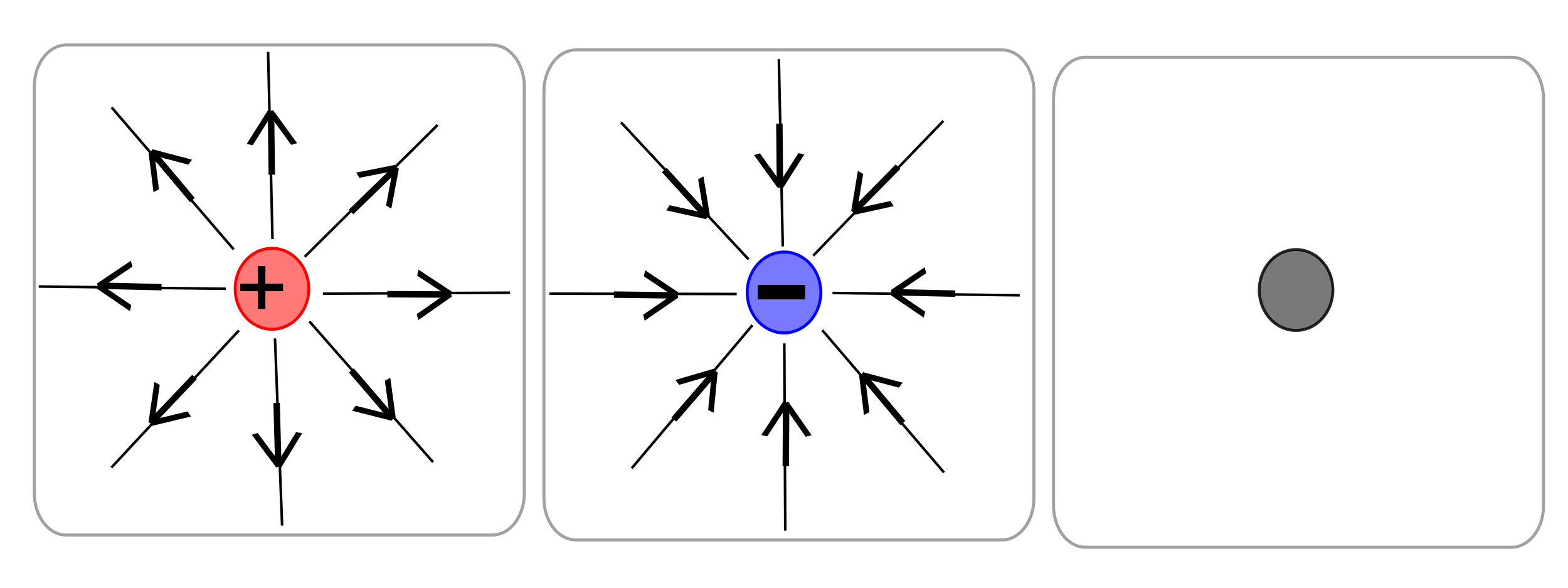
The equation that represents the value of the electric field strength, and its direction, is given by
Where E is the value of the electric field, F is the electric force, and q0 is the value of the positive test charge.
Another interesting thing to consider is that multiple charges can exist in a region and each one can create their own independent electric field. These fields interact in such a way that the net electric field is the vector sum of the individual fields. This is called the superposition principle.
If we replace F in the electric field equation with Coulomb’s law, we see that the magnitude of the strength of the electric field at a distance (r) from a point charge (q) is given by
One way of understanding electric fields is to apply Gauss’s Law for Electricity. Carl Friedrick Gauss, a German mathematician, described the interplay between electricity and magnetism in four famous laws called Maxwell’s equations. Specifically, Gauss’s Law for Electricity relates the electric flux through a closed surface to the charge enclosed by that surface. Electric flux is simply a measure of the amount of electric field passing through the surface. Generally, the equation for this law requires an understanding of calculus, but it can be often simplified as follows:
Here:
- represents the electric flux through a closed surface
- represents the charged enclosed by the closed surface
- is the permittivity of free space, a fundamental constant with a value of approximately 8.85×10⁻¹²
The key points to understand about Gauss’s Law for Electricity are:
- Closed Surfaces are used because it relates the behavior of the electric field over the entire enclosed region.
- Gauss’s Law is particularly useful when there is symmetry in the distribution of charge and the shape of the closed surface.
- Gauss’s Law works for all charge distributions as long as it respects symmetry conditions.
One application of electrical fields is in an electrical device called a capacitor. A capacitor is comprised of two conductive plates which are separated and each carrying electrical charge. This simple arrangement of charge produces an electric field between the charged plates and provides a way to store electrical energy.
Capacitors are used in nearly every electronic device you can think of, from cell phones to super computers. Another application of electric fields is in particle accelerators, where electric fields are manipulated to accelerate charged particles to high speeds.
Electric Potential (Voltage)
The electric potential is a scalar quantity that helps describe the energy associated with a given configuration of electrical charges within an electric field. The work done to move a charge against an electric field results in a change in electrical potential energy. The electric potential energy (U) of a point charge (q) in an electric field (E) is given by the equation:
, where V is the electric potential at that point.
Electrical potential, often referred to as voltage, is a scalar quantity that represents the electric potential energy per unit charge at a given point in space. The units of voltage are volts (V) named after Italian physicist Alessandro Volta, who invented the electric battery. Understanding voltage is vital to understanding electrical circuits, which are used in many fields of engineering.
For a point charge (q) at a distance (r) from the charge, the electric potential (V) at that point is given by:
, where k is Coulomb’s Constant.
For capacitors, mentioned in the section above, we can determine the electric potential difference across the plates by taking the charge (Q) on the plates and dividing by the capacitance (C), which is the capacitor’s ability to store electric charge.
Current, Resistance, and Ohm’s Law
Electrical current is the flow of electric charge in a conductor. Conductors are materials that readily allow electrical charges to move within or through them. Current is measured in units of amperes (A), named after the French physicist Andre-Marie Ampere (1775-1836), and is denoted by the symbol “I.” Electrical current can flow in two forms: direct current (DC), which flows in one direction in the conductor, and alternating current (AC), which periodically changes direction of flow within the conductor. It is the movement of electrons within a conductor that constitutes the electrical current.
Most electronic devices utilize direct currents for their circuitry, whereas houses and other buildings utilize alternating currents. The reason we use DC in electronics is because many of the components within these devices require a constant steady current that flows in one direction. The reason why buildings use AC circuitry is because DC is harder to produce, has greater power loss during transmission, typically produces more heat and fire hazards, and it costs more to convert between high and low voltages.
Resistance (R) is the opposition a material offers to the flow of electrical current. It is measured in ohms (Ω), named after the German physicist Georg Ohm, who studied circuits in 1827. Factors that affect the resistance of a conductor include the type of material the conductor is made of, length, cross-sectional area, and temperature.
Ohm’s Law is a fundamental principle of electricity that relates current, voltage, and resistance in a circuit. It is expressed as:
Where V is the voltage, I is the current, and R is the resistance. From the equation, we can see that Ohm discovered that the current flowing through a circuit is directly proportional to the voltage and inversely proportional to the resistance.
Magnetic Fields
Much like electricity, magnetism is an important phenomenon to understand in modern engineering applications. From production of electromagnets to trains that operate via magnetic levitation, the applications of magnetic forces have grown dramatically in modern history. It is no doubt that magnetism will gain increasingly important roles as engineers advance technology into the future.
First, it should be acknowledged that electric and magnetic phenomena almost always occur together; any time you have moving electrical charges there is a magnetic effect. Similarly, if you move a magnet near charged objects, the charges may be forced to move. The connected nature of electricity and magnetism gives rise to the term electromagnetism and the electromagnetic force is one of the four fundamental forces of the universe. Therefore, this section will delve into a basic understanding of key principles of magnetism.
Magnetic forces arise from the movement of charged particles. Specifically, the motion of electrons within atoms creates the effect. Electrons have a property called “spin,” which creates a magnetic moment. When many electrons align their magnetic moments in the same direction, the individual magnetic effects add up and create a macroscopic magnetic effect. These regions of aligned electron moments are called domains.
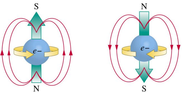
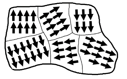
Magnetic moments created by electron spins Domains in ferromagnetic material
When ferromagnetic materials (iron, cobalt, and nickel) develop aligned magnetic domains, they can become permanent magnets. These magnets form when the ferromagnetic material is exposed to existing magnetic fields or electric fields that force the domains to align. Ferromagnetic materials can hold onto established magnetic properties for long periods of time, but not really forever.
This is different than temporary magnets, which only hold onto their magnetic effects for brief periods of time while the domain aligning force is still present or has only recently ended. An example of this is when an electric current flows through a coil of wire and it becomes magnetized; an electromagnet. In this case, the magnetic effect only lasts as long as the current is passing through the conductor. Unlike permanent magnets, temporary magnets can be made from many types of materials from conductive metals to organic substances.
A magnetic field is a region of space where a magnetic force is experienced by a magnetic material or a moving charge. Much like electric fields, magnetic fields are represented by magnetic field lines, which indicate the direction of the force on a positive test charge. In 1263, a French scientist named Pierre de Maricourt discovered that magnets have two distinct poles: North and South.
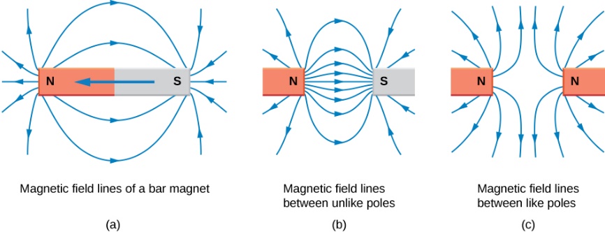
The names of the poles of a magnet are a reference to how magnets point along Earth’s magnetic field lines to the North Geographic Pole and South Geographic Pole of the planet. For a compass, or any other magnet, the north pole of the magnet points to the North Geographic Pole of Earth because the North Geographic Pole is actually the magnetic south pole of our planet.
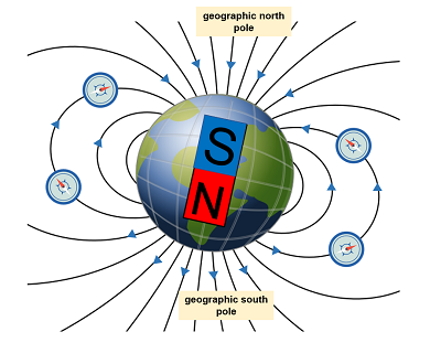
Similar to Gauss’s Law for Electricity, Gauss’s Law for Magnetism relates the magnetic field to the magnetic charge (also known as magnetic monopoles) within a closed surface. While magnetic monopoles have not been observed in nature, understanding this law helps to illuminate the mathematical aspects of magnetism and its interplay with electric fields. Basically, this law illustrates that the magnetic flux (B) across any closed surface is equal to zero. This may seem like a simple idea, but in practical application it is useful for doing things like figuring out the strength of the magnetic field produced by a piece of current carrying wire, which can have severe implications for electronics engineering. Also, this law verified that there are no such thing as magnetic monopoles. This is significant for our understanding as we move forward to examine how we can predict the force exerted on a charged object moving through electric and magnetic fields.
Lorentz Force Law
Hendrik Lorentz, a Dutch physicist, determined the mathematical relationship needed to predict the force (F) acting on a charged particle (q) moving with a velocity (v) through an electric field (E) and a magnetic field (B). This law involves vector mathematics because the force, electric field, velocity, and magnetic field are all vector quantities. In fact, the only variable that is scalar in this equation is charge (q). The equation is:
where “x” is a vector cross product and the mathematical operation is typically a resolution of a matrix in terms of Cartesian components. So, in three-dimensional space the force is given by:
The directions of the vectors can be predicted with the right-hand rule for Lorentz Force, as shown below. The current density is basically the direction of motion of the charged particle.
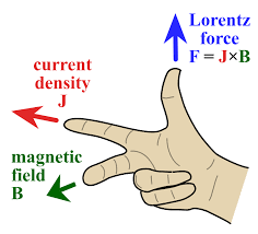
Understanding magnetic force is crucial for explaining the behavior of magnetic systems, the motion of charged particles, and to design many technicalities devices. These laws have been used to design such things as electric motors, magnetic resonance machines (MRIs), magnetic levitation systems, and magnetic data storage devices (e.g. computer hard drives).
Faraday’s Law of Electromagnetic Induction
One of the most important applications of electric and magnetic theory is the production of electrical current. The process of producing electricity from a magnetic field was independently discovered by two scientists: Michael Faraday in 1831 and Joseph Henry in 1832. Faraday was the first to publish the results of his experiments. In this notebook, he described an experimental demonstration of electromagnetic induction. He wrapped two wires around the opposite sides of an iron ring. Based upon his recent work with electromagnets, he predicted that when current was applied to one of the wires, a sort of wave would travel through the ring and cause some electrical effect on the opposite side. When he applied the current to the first wire, he did in fact measure a current being produced in the second wire as a result of a change in magnetic flux that occurred. What he had proven was that changing the magnetic field across a conductor could create electrical current. This discovery is the basis for modern day generators and electrical transformers.
The equation for Faraday’s Law of Induction is
Here:
- represents the induced voltage
- represents the number of loops
- is the magnetic flux
- is the change in time
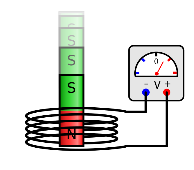
It should also be noted that the negative sign in Faraday’s Law is a result of the discovery, by Russian physicist Emil Lenz in 1834, that the induced current will always flow in a direction that opposes the change in magnetic flux that produced it.
Circuits
Electrical circuits are the backbone of modern technology, powering everything from simple electronic devices to complex industrial systems. Understanding the fundamentals of electrical circuits is crucial for engineers, scientists, and anyone working with electronic systems. This section provides an introduction to the basic concepts and principles that govern electrical circuits.
Components of Circuits
All circuits, no matter how simple or complex, are comprised of three basic components: a voltage source (like a battery), current carrying conductors (such as wires), and resistive devices (things that do electrical work). Remember, current is the flow of electric charge through a conductor. It is the voltage source that creates the potential difference that pushes current through the circuit. The devices that do the electrical work create resistance to the flow of current. In the process of creating resistance, these devices use energy and produce heat.
Historically, before a working knowledge of electromagnetic forces, electrons, and protons was formulated, scientists thought of electricity as the flow of current from the positive terminal of a battery, through the circuit, to the negative terminal. This is called “conventional current” and is the framework still used by most scientists, engineers, and electricians to this day.
Our modern understanding of electromagnetic forces between protons and electrons illustrates the physical fallacy in this historical/conventional framework. As already discussed, electrons are very small negatively charged particles. They are roughly 1,835 times smaller than protons in terms of mass. As such, electromagnetic forces actually push electrons away from the negative terminal, through the circuit, and back to the positive terminal (at least for direct current situations). This “true” current, which follows modern laws of electromagnetism, is called the “electron current.”
Despite the fact that electron current is more scientifically precise, we still typically use conventional current for real world applications such as circuit analysis; mostly as a nod to the historical development of our understanding of electricity and conventions that were established over time. However, electron current is sometimes used in semiconductor physics and electron beam applications.
Ohm’s Law, V=I*R, becomes our most powerful mathematical tool when designing and analyzing circuits. From Ohm’s Law we can see that the higher the voltage in our circuit, the higher the current assuming a constant resistance. Also, the higher the resistance, the lower the current assuming a constant amount of voltage. These simple ideas help engineers produce the right amount of current for the electrical devices they want to power.
Types of Circuits
There are only three types of circuits: series circuits, parallel circuits, and combined circuits. Combined circuits are actually circuits comprised of both series and parallel circuit elements. So, if you master the workings of series and parallel circuits, designing and analyzing combined circuits is nothing more than the addition of those elements.
In a series circuit, all components are connected in a single conductive pathway. The same current (I) flows through each component and the total resistance (RT) is the sum of the individual resistances of the devices in the circuit. The voltage (Vn) across each “nth” resistor adds up to the total voltage of the initial voltage source (the battery). The electrical power (P), given in units of watts (W), of a resistive device is the product of the current (I) passing through it and the voltage drop (Vn) across the device or the product of the current squared (I2) and the resistance (R).
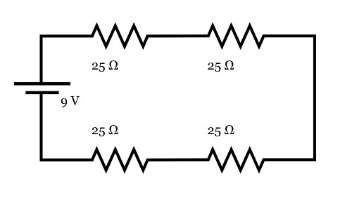
So, for the circuit above:
- RT = 25Ω + 25Ω + 25Ω + 25Ω = 100Ω
- I = V/RT = 9V/100Ω = 0.09A
- The voltage drop across all resistors is equal because their resistances are equal, so V1 = V2 = V3 = V4 = I*Rn = 0.09A*25Ω = 2.25V
- The sum of all voltage drops is V1 + V2 + V3 + V4
= 2.25V + 2.25V +2.25V +2.25V = 9V,
which is the same as the batterie’s voltage.
- The power of each electrical device is equal since they have the same current and voltage drops, so P1 = P2 = P3 = P4 = I*Vn = 0.09A*2.25V = 0.2025W
In parallel circuits, components are connected in multiple current carrying pathways. The reciprocal of the total resistance is equal to the sum of the reciprocals of the individual resistances. The voltage across each resistor is the same, and the total current is the sum of the currents through each individual resistive branch of the circuit.

So, for the circuit above:
- 1/RT = 1/(25Ω) + 1/(25Ω) + 1/(25Ω) + 1/(25Ω) = 4/(25Ω)
Therefore, RT = 6.25Ω
- V1 = V2 = V3 = V4 = 9V
- The total current in and out of the battery is IT = V/RT
= 9V/6.25Ω = 1.44A
- Since the resistance is the same in all branches, the currents should be equal as well. So, I1 = I2 = I3 = I4 = V/Rn = 9V/25Ω = 0.36A
- The sum of all individual currents is I1 + I2 + I3 + I4
= 0.36A + 0.36A + 0.36A + 0.36A = 1.44A,
which is the same as the current in and out of the battery.
- The power of each electrical device is equal since they have the same current and voltage drops, so P1 = P2 = P3 = P4 = I*Vn = 0.36A*9V = 3.24W
Some interesting things to note from the examples above:
- The total resistance in the parallel circuit was much lower than that of the series circuit, although we used four resistors of equal resistance in each circuit. In general, parallel circuits end up with lower resistance!
- Current was much higher in the parallel circuit due to the lower resistance.
- The devices had more power in the parallel circuit due to increased current and equal access to the voltage source.
- If one resistor fails in a series circuit, the circuit is “open” and none of the remaining resistors will get any current nor be able to function.
- If one resistor fails in a parallel circuit, the remaining resistors still have voltage and will continue functioning.
Since combination circuits combine elements of series and parallel circuits, analyzing these circuits often involves breaking them down into simpler series and parallel components. Doing this takes a bit of practice. One rule of thumb is that it is often best to resolve parallel branches down into simple series elements and eventually bring the entire circuit down to one equivalent resistor, piece by piece. As we proceed with the analysis of combined circuits, it is common to end up with a set of linear equations that are solved simultaneously for the unknown variables.
For example, in the circuit below we would start by reducing the parallel branch containing R2 and R3 into a single equivalent resistor in series with R1 and R4. We would then add R1, the equivalent resistor replacing R2 and R3, and R4 together to make one individual equivalent resistor for the entire circuit. From here, we would apply Ohm’s law and use the battery’s voltage and the circuit’s total resistance to determine the current moving in and out of the battery.
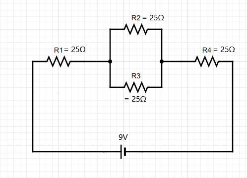
But from there, how do we determine the actual voltage drop and current through each individual resistor in the original circuit? Two laws that help with analysis of more complex combined circuits are Kirchhoff’s Voltage Law (KVL) and Kirchhoff’s Current Law (KCL). These laws were first descried in 1845 by German physicist Gustav Kirchhoff. These laws are widely used in electrical engineering and are sometimes called Kirchhoff’s rules or Kirchhoff’s laws. KVL states that the sum of the voltages in any closed loop of a circuit is zero. This is true due to the law of conservation of energy. KCL asserts that the total current entering a junction in a circuit is equal to the total current leaving the junction. This law is based on the principle of conservation of charge.
Applying KVL to our example above, we know that the sum of voltages in and out of the battery must be zero. Therefore, the sum of the voltage drops across all resistors must be equal to the battery’s voltage. We also know that R2 and R3 have the same voltage available to them because they are in parallel. Since the voltage drop across R2 and R3 is equal, the voltage drop across R4 is equal to the battery voltage minus the voltage drop across R1 and the voltage drop across R2 or R3.
Applying KCL, we also know that the current passing through R1 is equal to the current entering into the parallel section with R2 and R3. When the current hits the junction of the parallel section, resistors R2 and R3 split the current. In this case they will split the current equally because the resistors have equal values, but this is not always the case. When the resistors in a parallel branch don’t have equal values, we use Ohm’s law to determine the individual current passing through the resistors based upon the voltage drop of the parallel branch and the individual resistance of each resistor. When the current leaves the parallel branch, it is once again equal to the current that entered the parallel section, which is equivalent to the current passing through R1. This is the same current that ultimately passes through R4 and back to the battery.
Now, let’s go through this mathematically. As discussed, the first step is to simplify the circuit by replacing the two parallel resistors, R2 and R3, with a single resistor of equivalent resistance. Two 25Ω resistors in parallel is equivalent to one 12.5Ω resistor. Thus, the two parallel resistors, R2 and R3, can be replaced with a single resistor with a resistance of 12.5Ω. This resistor will then be in series with R1 and R4 and the total resistance of the circuit becomes a simple sum of the three resistors; R1, the new equivalent resistor replacing R2 and R3, and R4.
Ohm’s Law can now be used to determine the total current in the circuit. To do this, we use the battery’s voltage and the total resistance of the circuit.
The calculation above represents the current at the battery’s location. Yet, resistors R1 and R4 are in series with the battery, so they have the same current passing through them as the battery’s total current.
For parallel branches, the sum of the current in each individual resistor is equal to the current outside of the parallel branch. Therefore, I2 + I3 must be equal to 0.144A. As mentioned above, since R2 = R3, the current in both is equal.
Now we can use the current at each individual resistor to determine the voltage drop across each resistor.
Finally, we could determine the power of each resistor by multiplying its voltage drop by the current passing through the resistor.