The MRC-1000 is the base upon which all teams competing in the Robot Gladiator League build their battle systems. The chassis includes a modular drivetrain, electrical power, onboard pneumatic system, dual operator controls and safety systems. It uses an aluminum main chassis protected by high density polymer armor to survive the rigors of robot combat.
Key Features:
CNC machined aluminum chassis for high strength
CNC machined HDPE protective armor panels for impact absorption
Extensive use of 3D printed PETG parts for easy replacement and customization
Minimal threaded parts for easy maintenance and hardware replacement
External tool access to most replaceable and adjustable parts
Dual transmitter operation so that pilot and battle systems are separated
Up to 48 channels of radio control (20 included as standard)
Onboard air compressor with 120psi safety shut-off switch and remote start/stop
Onboard air tank, relief valve, pressure gauge and pressure regulator
5-way electronic pneumatic valve with dual air outputs
12.6-volt Lithium Polymer main battery with over 100 watt-hours of capacity
Resettable circuit breaker with manual safety shut-off
Dual battery provisions for teams using electric battle systems (parallel)
HTD 5M belt drive pulley based drivetrain
Adjustable wheel position
Rubber wrapped polymer drive wheels with ball bearings
MAGSTOP disabling system
UHMW polymer front skid feet
3/8” mounting provisions for battle system components (front and side panels)
Clean exterior design ready for team decorative styling
Decorative lighting provisions
Full 3D modeled design with files available for easier customization
Expandable through additional modules (continual development)
Component Overview
*Right or Left is always from the perspective of someone standing behind the robot looking forward
chassis
Aluminum Chassis Parts
(Front View)
MRC-FP: Aluminum Front Panel
MRC-RP: Aluminum Rear Panel
MRC-SPL: Aluminum Side Panel Left
MRC-SPR: Aluminum Side Panel Right
MRC-IPL: Aluminum Inner Panel Left
MRC-IPR: Aluminum Inner Panel Right
HDPE Chassis Armor
(Front View)
MRC-PPF: Polymer Panel Front
MRC-PPR: Polymer Panel Rear
MRC-PPRS: Polymer Panel Right Side
MRC-PPLS: Polymer Panel Left Side
(Front View of Assembly)
3D Printed PETG Chassis Parts (Not to Scale – Colors May Vary)
MRC-RUB: Rear Upper Mounting Block (Qty 2)
MRC-RLB: Rear Lower Mounting Block (Qty 2)
MRC-FLB: Left Front Mounting Block
MRC-FRB: Right Front Mounting Block
MRC-FG: Fan Grill MRC-TBM: Top/Bottom Mount (Qty 14)
MRC-TBM: Top/Bottom Mount (Qty 14)
MRC-PST: Pinion Stops (Qty 2)
MRC-TBMAC: Top/Bottom Mount Air Compressor Location
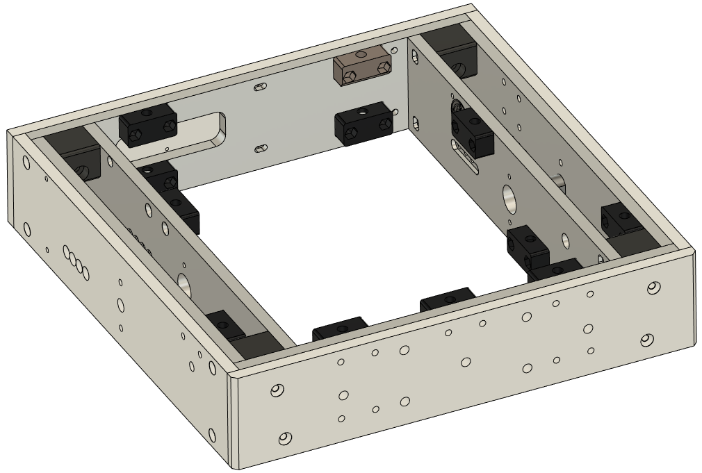
3D Printed PETG Chassis Parts (As Assembled)
(Front Upper View)
(Rear Upper View)
(Bottom Right View)
(Bottom Left View)
Drivetrain assemblies
The drivetrain of the MRC-1000 consists of two independent 400 Watt motors attached to drive wheels using a single stage timing belt pulley system. The pulley and belt type used is called HTD 5M and is found in many lengths and widths across various industries and applications. The “standard” setup is a 12-tooth pinion pulley on the motor driving a 60-tooth drive pulley on the wheel using a 350mm belt. This puts the wheel at the closest position to center of the chassis. Optional drive belts are available in 375mm, 400mm and 425mm sizes. As you increase belt size you need to move the wheel rearward. This shifts the balance of the chassis and adjusts its driving characteristics. Generally speaking, the chassis will be more maneuverable with the wheels forward and more stable with the wheels rearward. The actual balance is dependent on where the weight from your battle systems is placed on the chassis.
Drive Belt
Electrical system
Battery
The electrical system of the MRC-1000 starts with a Lithium Polymer (LIPO) rechargeable battery pack. This pack consists of 3 individual cells of 3.7 volts wired in series and wrapped in a polymer case to appear as a single battery with a nominal voltage of 11.1 volts. The nominal voltage is representative of the average voltage produced over the discharge of the battery pack. In practice the voltage varies from full charge of 12.6 volts down to the lowest useful charge at 10 volts. As your battery charge is used the robot not only loses remaining runtime but also total available power due to this drop in voltage. You should do everything possible to conserve this power for when it will provide the biggest advantage in competition. A second battery provision is made for systems using electrically powered battle systems. This battery is identical to the main power battery but connects directly to the battle system motor.
*WARNING*
Never let the battery pack drop below 10.5 volts at rest. LIPO batteries will lose the ability to recharge if they are discharged too much. It is good practice to recharge your battery any time it is below 11.5 volts. Make sure to start each match with a fully charged battery.
The relationship of voltage to useful charge remaining is approximately:
These 3D printed parts are used to hold the battery in place. The slots accept Velcro straps to secure the battery. There are mounting provisions in the MRC-1000 bottom plate for 2 batteries if you remove the pneumatic controls.
Circuit Breaker
The electrical power flows from the battery through a circuit breaker which reduces the chance of an electrical fire should the main battery become severely overloaded. This protection is a last resort and cannot eliminate fire risk in all circumstances. The circuit breaker has a manual trip function which serves as a safety shut off for all electrical power to the rest of the chassis. There are mounting points for additional hardware incorporated within the circuit breaker mount.
5V DC to DC Converter
The DC to DC converter takes the main battery voltage and reduces it to a stable 5-volts required by the control system of the MRC-1000. This saves the weight and complexity of a second battery. This converter is attached to the side of the circuit breaker mount. The main power battery is connected to the 12V side of the converter (labeled Input) and the 5-volt systems connect to the 5V side of the converter (labeled Output).
Power Distribution Block (PDB)
The power distribution block will split the power from the main battery to all of the sub-systems that require electrical power. There are extra power locations for adding additional features.
Electrical Connectors
Various types of electrical connectors are used throughout the MRC-1000 systems. The types and specifications are listed below:
Servo Connector (3-pin plug) Current Capacity < 3A
Used for: ESC control, Air compressor on/off, Battle switch
3.5mm Gold Bullet <30A
Used for: Air Compressor Pressure Switch
XT Series <30A <60A <90A (Not Used)
Used for: Receivers, Air Valve (XT30), ESC Power, PDB, Fan, Air Compressor, 5V Converter, Air Valve Power (XT60)
MR Series <30A <60A
Used for: Motor to ESC (MR60), Magstop to ESC (MR30)
EC5 <120A
Used for: Main battery to PDB
Air System
Air Compressor
The air compressor uses an electric motor to drive a piston inside a cylinder to produce air flow. When outflow is restricted the air pressure in any downstream devices will increase. The compressor in the MRC-1000 is rated to create up to 120 pounds per square inch (psi) of air pressure. You are able to start and stop the compressor remotely from the transmitter. There is an electronic pressure shutoff switch that monitors the high-pressure side of the system and will shut off the compressor automatically at 120psi and restart it at 90psi. If your air lines are damaged in competition you should remotely shut off the compressor to keep it from continuously running. Running continuously creates extra heat and uses battery charge that could damage components.
Remote Shutoff and Pressure Switch
As mentioned above there is a remote electronic shutoff and electronic pressure switch in the air compressor circuit. Both of these operate on 12V. They are wired in series so that either or both can shut down the compressor. You should not have to adjust these items.
Pressure Switch w/ Mount
QR1060 Remote Shut-off Switch (Sits on top of 5-way valve)
(Located near compressor)
Air Tank (Accumulator)
The air tank is capable of containing a volume of 574ml of compressed air at up to 125psi. It is called an accumulator because it stores air pressurized by the compressor even when the compressor is not running. In this way it operates much like a rechargeable battery using air instead of electricity.
There are several components attached to the air tank that serve important functions in the air system.
Push-To-Connect (PTC) – Allows air lines to easily interface with pneumatic components
Tank Mount – Cradles the tank and has provisions for Velcro straps to hold tank in place
Pressure Relief Valve – A pushbutton to manually release air from the high-pressure side of the system
Pressure Regulator – Reduces air pressure from the tank before sending it through the valves and battle systems. This is used to tune the performance of your devices.
Pressure Gauge – A visual indicator of the pressure after the regulator. This allows for consistent adjustment and testing.
5-Way 2-Position Air Valve
The air valve connects to the low-pressure side of the pressure regulator and directs air to pneumatic devices according to the path of the air lines. The pneumatic cylinders used in RGL require two air lines to work properly.
Control System
Transmitters
Taranis QX-7 ACCESS (Qty 2)
These transmitters have multiple controls that can be manipulated and an internal computer that can mix and modify these movements into desired control outputs. The outputs are then sent via radio signals to the receivers in the MRC-1000.
As delivered, the WHITE transmitter is used by the pilot to control movement while the BLACK transmitter is used by the battle system operator (BSO) to operate systems. These transmitters run an open source code called OpenTX which has a PC programming interface as well as internal menu driven programming for all features. There are many tutorials online describing the use of OpenTX to operate a variety of radio controlled vehicles.
Receivers
FrSky Archer ACCES R10 PRO (Qty 2)
These devices receive radio signals from the transmitters and activate controls connected to the outputs. There are 10 standard outputs per receiver and up to 24 outputs available using a BUS system. There are 2 receivers in the MRC-1000. Each receiver is paired with a specific transmitter.
BattleSwitch
The Battleswitch is a 10-Amp relay that can be switched by remote control. The main use in the MRC-1000 is for actuating the electronic air valve. Additional uses could be remote controlled lighting, small motor actuation or controlling any other low power electrical device. You can add Battleswitches to extra output channels on the battle system receiver to control additional functions.
Electronic Speed Control (ESC) (Qty 2)
The ESC is a device that controls the speed and rotation direction of a motor via signals received signals from various sources. On the MRC-1000 standard arrangement the ESC uses a PWM signal from the receiver paired with the pilot transmitter to operate the motors. The ESC used in this kit is fully programmable via USB and PC software.
If you choose to build an electric motor powered battle system using the same motor system that drives the chassis, you will need to add an ESC for each new motor. The receivers can easily accommodate additional controls but be careful not to overload the battery or PDB. It is recommended that you power the additional motors directly from a separate battery.